Reaction turbine
In Reaction turbine major portion of the pressure loss takes place in the rotating wheel. Fluid entering the rotor around its entire circumference is in action. So its rotor need to be so large as compared to the impulse turbine of same power.
In reaction turbine, water enters the wheel under pressure and flow over vanes. As the water, flowing over the vanes, is under pressure, therefore wheel of the turbine runs full and may be submerged. The pressure head of water, while flowing over tha vanes, is converted into velocity head and is finally reduced to the atmospheric pressure, before leaving the wheel.
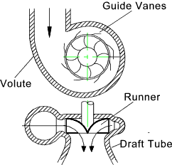
Main Components of a reaction turbine
A reaction turbine has the following main components.
- Spiral casing
- Guide mechanism
- Turbine runner
- Draft tube
Spiral casing
The casing of reaction turbine is designed in such a way that its cross sectional area goes on reducing uniformly around the circumference. The cross sectional area is maximum at the entrance and minimum at the tip. Due to this, the casing will be of spiral shape. That is why it is called spiral casing or scroll casing. The water from a pipeline is distributed around the guide ring in a casing.
The material of the casing depends upon the head of water. If head is upto 30 meter then concrete should be used. If head is upto 100 meter then welded rolled steel plate should be used. If it is more than 100 meter then cast steel should be used for casing.
- Guide mechanism
This is the arrangement of blades and vanes which will guide the water to move towards runner.
The guide vanes are fixed between the two rings in the form of a wheel. This wheel is fixes in the spiral casing.
Functions of guide vanes
- Guide vanes allow the water to enter the runner without shock. Guide vanes keep relative velocity at inlet of the runner, tangential to the vane angle and thus results in entering of water without shock.
- Allow the water to flow over them without forming eddies.
- Allow the required quantity of water to enter the turbine. This is done by adjusting the vanes.
All the guide vanes can rotate about their respective pivots. Pivots are connected to the guided ring or regulating ring. This ring is connected to the regulating shaft by means of two regulating rods. Guide vanes may be closed or opened by rotating the regulating shaft, thus allowing required quantity of water to flow. The regulating shaft is operated by a governor whose function is to govern the turbine. Governor function is to keep the speed constant at varying loads.
Guide vanes are generally made of cast steel.
- Turbine Runner
The rotating wheel of the reaction turbine is known as runner. Runner consists of many curved plates welded with circular discs. For small diameter they are casted as single units.
The runner is keyed to a shaft, which may be vertical or horizontal. If the shaft is vertical, it is called a vertical turbine. Similarly if shaft is horizontal, it is called as horizontal turbine.
The surface of the runner is mde very smooth to minimize frictional losses. The runner may be cast in one piece or may be made of separate steel plates and welded together.
For low heads, the runner may be made of cast iron. But for high heads, the runner is made of steel or alloys. When the water is impure, special alloys are used.
Draft tube
The water, after passing through the runner, flows down through a tube called draft tube.
- It increases the head of water equal to the height of the runner outlet above the tail race.
- It increases efficiency of the turbine.

Reference :
A textbook of hydraulics, fluid mechanics and hydraulic machines by R.S. Khurmi
Leave a Reply